

Laser Welding Cracks: Why They Happen and How to Prevent Them
You switch on the fiber laser, set the travel speed, and run a beautiful, continuous bead across the joint. It looks perfect to the naked eye. But an hour later, you hear a distinct “ping” from the cooling rack, or worse, your QA department flags a hairline fracture under dye penetrant testing.
The very things that make this technology profitable—extreme energy density and rapid travel speeds—create violent thermal gradients. This rapid heating and quenching cycle traps immense stress inside the metal. If you are blindly adjusting power and speed without understanding the metallurgy of the joint, you will continue to scrap parts.
To permanently stop laser welding cracks, you have to stop treating the symptom and start diagnosing the metallurgical root cause. Here is how to analyze the failure, verify your steel chemistry, and adjust your parameters to keep the weld pool stable.
Table of Contents
Are You Seeing Hot or Cold Cracks?
Not all fractures are created equal. Before touching the machine interface, look at exactly when and where the joint failed.
Hot Cracking (Solidification Cracks)
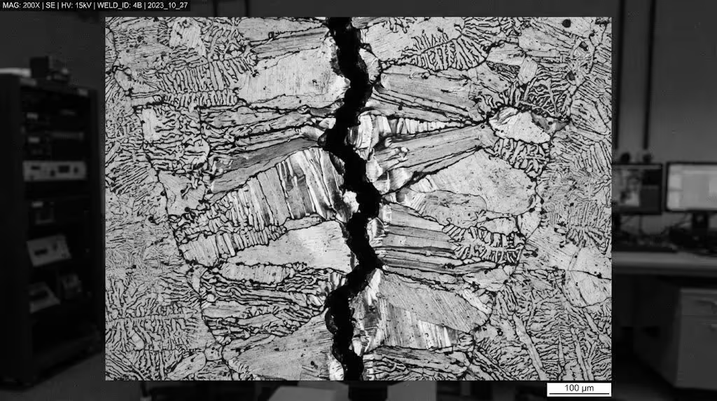
These happen instantly. As the liquid metal turns solid, it shrinks. If the weld pool contains impurities with lower melting points, these impurities remain liquid longer than the surrounding steel, accumulating at the grain boundaries. When the weld shrinks, it literally tears these weakened boundaries apart. You will almost always see hot cracks running directly down the centerline of the weld bead.
Cold Cracking (Delayed Cracks)
These are the silent killers. A cold crack can appear hours or even days after the part has returned to room temperature. They typically manifest in the Heat Affected Zone (HAZ) rather than the weld center. This failure is driven by a brittle microstructural transformation (forming hard martensite) combined with trapped hydrogen. If you want to understand the exact mechanism of this delayed failure, the breakdown of hydrogen embrittlement and steel stress on Wikipedia provides the exact chemical timeline of how hydrogen atoms force the steel lattice apart.
Why Material Verification Dictates Laser Welding Material Compatibility
The most common mistake on the shop floor is assuming all steel behaves the same under a laser beam.
If you are joining standard Q235B structural steel, the low carbon content makes it incredibly forgiving. You can often run fast autogenous welds (no filler) without issue.
However, if you put high-carbon or alloy steels like AISI 4140 or H13 tool steel under that same beam, the extreme quenching rate turns the HAZ into brittle martensite instantly. To understand why this happens, you must calculate the steel’s hardenability. Engineers rely on the Carbon Equivalent (CE) formula to predict crack sensitivity before striking an arc. If your CE is above 0.40%, welding without strict thermal control is a guaranteed failure.
Before you weld, pull the Material Test Report (MTR). Check the exact percentages of Sulfur (S) and Phosphorus (P). These are the main culprits for hot cracking. If your MTR shows sulfur levels exceeding 0.03%, the material is highly sensitive to centerline tearing. Do not try to fix a bad MTR with machine parameters.
How Laser Welding Parameters Optimization Reduces Thermal Stress
Once you confirm the steel chemistry is safe, you can look at the machine. Most operators run the travel speed too high to maximize throughput.
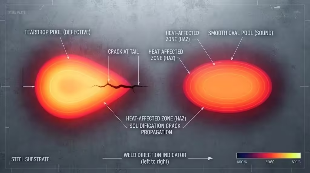
At excessively high speeds, the liquid weld pool elongates into a teardrop shape. As the teardrop solidifies, the thermal shrinkage forces converge violently at the sharp tail of the pool, creating a textbook centerline hot crack.
According to failure analysis guides on identifying laser welding defects, slowing the travel speed allows the weld pool to form an elliptical (oval) shape. An elliptical pool distributes the shrinkage stress evenly across a wider trailing edge, neutralizing the pulling force that causes tears.
You must also control the focal position (defocus). If your beam is perfectly focused on the surface (zero defocus), it creates a deep, narrow keyhole. Deep keyholes trap gas and create severe transverse stress. By applying a slight positive defocus (moving the focal point slightly above the material surface), you widen the beam footprint. This creates a wider, shallower “bowl” shaped weld that accommodates thermal expansion much better.
3 Actionable Steps to Prevent Cracks on the Shop Floor
If you are dealing with challenging alloys or thick sections, parameter tweaks alone won’t save you. You need to intervene in the thermal cycle.
1. Mandate Pre-heating and Post-Weld Slow Cooling
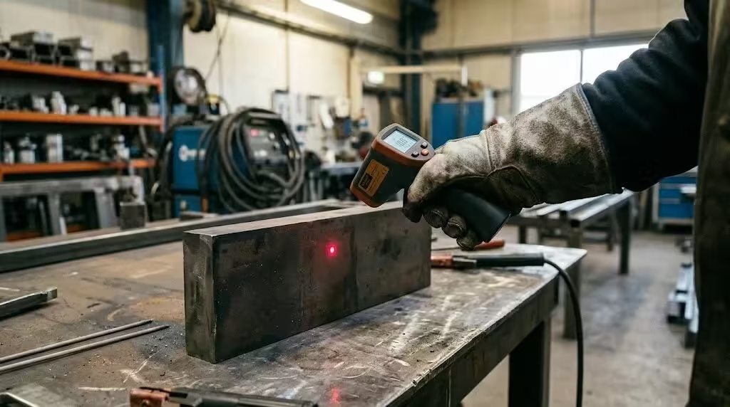
If you are repairing injection molds made of H13 tool steel, welding at room temperature will cause the surrounding cold metal to act like a heat sink, flash-freezing the weld. As seen in real-world discussions among fabricators regarding welding H13 tool steel without cracking, preheating the part to at least 300°C (570°F) is non-negotiable. This slows down the cooling rate, allowing the steel to form a softer, ductile microstructure rather than brittle martensite.
2.Feed the Right Filler Wire
Autogenous welding relies entirely on the parent metal. If the parent metal has poor crack resistance, the weld will fail. By introducing a filler wire with lower carbon and higher ferrite-forming elements, you actively dilute the carbon content of the weld pool. This metallurgical shift gives the joint the elasticity it needs to survive the cooling phase.
3.Optimize Shielding Gas Flow
More gas does not equal a cleaner weld. If your Argon flow rate is too high, the turbulent gas physically blows the liquid metal out of the keyhole, or worse, drags atmospheric oxygen and moisture into the pool. Moisture introduces hydrogen, leading directly to cold cracking. Dial back the flow meter until the gas forms a gentle, laminar shield over the melt zone.
Stopping laser welding cracks requires looking past the control screen and respecting the chemistry of the steel on your table. Check the MTR before you program the robot. Manage your cooling rates, keep your weld pool elliptical, and introduce filler wire when the carbon equivalent demands it. A controlled thermal cycle is the only way to guarantee a joint that survives inspection.
FAQ
Why does my weld crack right down the middle immediately after the beam passes?
This is a solidification crack (hot crack). Your travel speed is likely too fast, creating a teardrop-shaped weld pool, or your parent material has excessive sulfur/phosphorus content. Slow down the travel speed to round out the weld pool.
Can I stop cold cracking just by using Argon gas?
No. Argon displaces atmosphere, but it cannot change the cooling rate of the metal. If you are welding alloy steels with a high Carbon Equivalent, cold cracking will still occur due to rapid quenching. You must preheat the material to prevent martensite formation.
How do I fix a crack if it already happened?
You cannot simply weld over it. The crack contains oxides that will ruin the next pass. You must physically grind or machine the crack out entirely to reach clean, solid base metal before attempting a repair pass, ideally using a compatible filler wire. Detailed guidelines on managing solidification cracking defects dictate that total removal of the flawed geometry is mandatory.